The below information will help explain how to add a high-temperature transmitter to a Standard Alloy SureSite that didn’t have one when originally built at Gems.
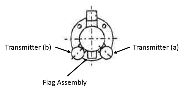
SureSite transmitters are clamped onto the stainless-steel housing so it is a simple install. However, it is important to specify and order the correct transmitter, so it matches your existing SureSite correctly and indicates properly. High temp transmitters must be installed adjacent to the flag assembly, on either side. If it is not within this orientation the reed switches within the transmitter may not close. See the below image for further detail, in position (a) or (B).
First step is to determine your indication length, as this will dictate the transmitters length and p/n. For ‘BA’ style Side-Side mounted units, it is the center to center dimension between those two side connections. For other configurations you can measure the flag assembly and subtract 2” from this dimension, as we typically build the flag assemblies an inch longer on either end.
The distance between these two marks in inches will dictate how long we make the transmitter and the complete p/n. Since the junction box comes attached to the transmitter, you can have this configured at the top or the bottom. Below shows each configuration.
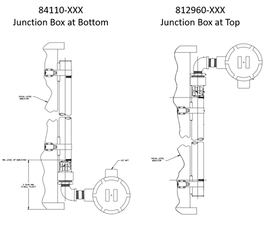
For example, if your measurement is 36”, the p/n will be 84110-036, with the junction box at the bottom. 812960-036 is the p/n with the junction box at the top. Both will have a 4-20mA output.
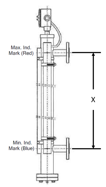
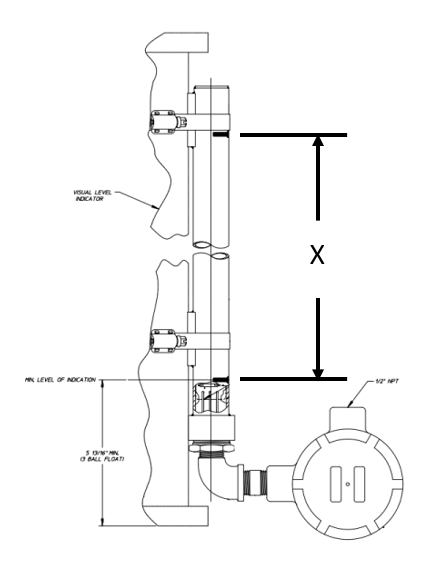
After receiving your transmitter, you will clamp it onto the housing and line the indication marks (blue and red) with your flag assembly indication points. The blue indicates the bottom portion of the indicating level, and the red marks where the indication level stops. ‘X’ shows the indication length below.
Once you have determined your p/n please contact Gems for pricing and availability.